|
God
has
chosen
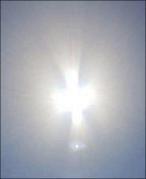
the Land of the Holy Cross (Anguera-Brazil)
to announce to the world what will happen

and CROP CIRCLEs to give
the last chance to human being
|
|
click here for
 complete page
click for
the
2019 calendary -
rev. 3 -
5-12-2019
Rev.
29 - 23-8-2018 -
CROP
CIRCLES TELLS THE END OF TIMES
Rev 3-
20-8-2018
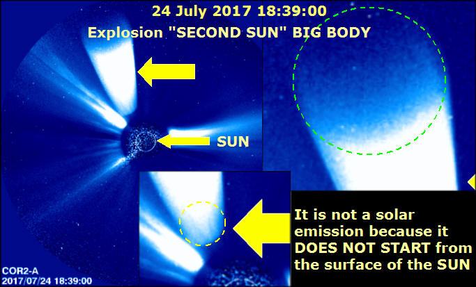
SECOND SUN history given by
NASA STEREO AHEAD satellite and LASCO
|
|
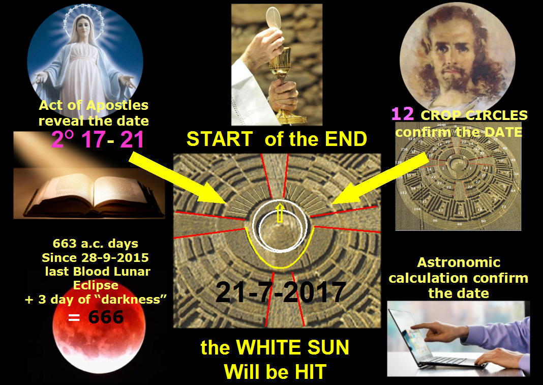
17-8-2017 the END of
TIMES COMET STAR CROP CIRCLE -
click on the figure
ver. 25
19-8-2018
|
|
 Jesus will appear in the GREAT WARNING to all the world
rev. 7 - 20-8-2018
|
|
1-1-2018 click
for videos in
COLOMBIA .
29-1-2018
VIDEO in GLASGOW

GRAN FINALE English -
SECOND SUN and GREAT WARNING are BOUND together
Second Sun orbit: calculation was perfectly made HERE
the NEW PATH

|
|
click
on the figure
for the video - here the direct channel
this
photo shows it at a distance of 20 milions/Km - 12.5 mil/miles
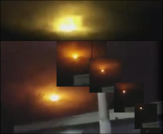
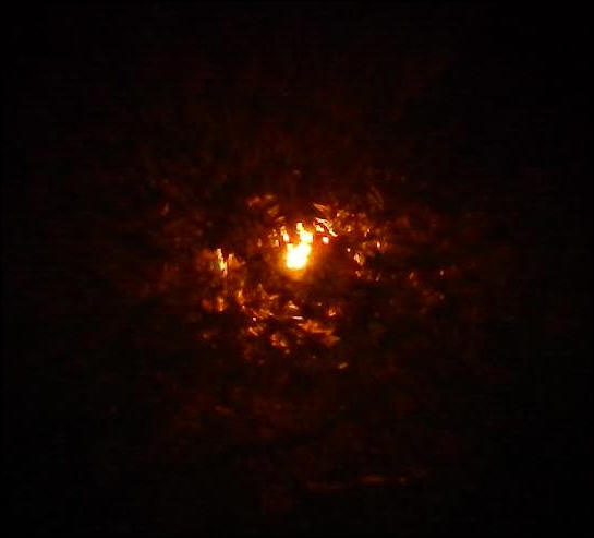
SECOND SUN
IS ALREADY HERE -
a CROP
tells the last 3.5 turns round the SUN
rev.
10

the
SECOND SUN the
CELESTIAL BODY taken DURING NIGHT TIME
on 26-6-2017 (see
analysis)
click here for
complete page
|
|

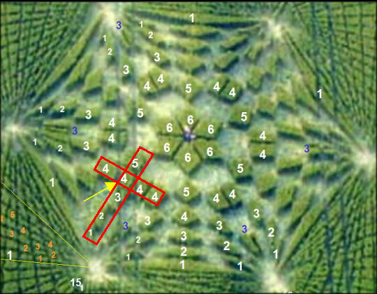
ISRAEL DESTRUCTION complete
decoding - click on figure
ver. 7

|
|
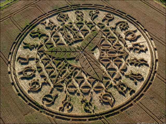
HOLY FAMILY against Antichrist: the COMPLETE 12-8-2016
CROP CIRCLE
decoding
|
|
26 OCT
VIDEO in OHIO SHOWs a collapsing star into a BLACK
HOLE
HERE NEARBY
so the next could be a WHITE DWARF sucking
SUN ENERGY exploding into a SUPERNOVA
video REV.6
PDF FILE
REV.8
rev. 8
Second Sun orbit: calculation was perfectly made HERE
the NEW PATH
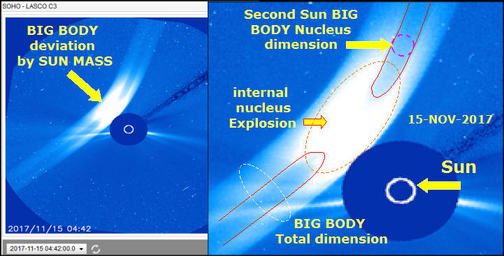
NASA
satellite
STEREO AHEAD CORONAGRAPH 2 - the proof of the SECOND
SUN/ STAR PASSING - deleted hours of recordings
|
|
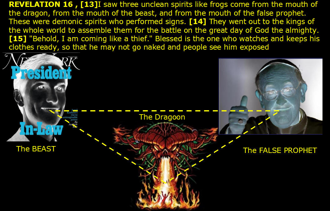
JARED KUSHNER is an ENEMY
of the HUMAN POPULATION - and
the 666 RFID is belonging from them -
VIDEO
|
|


The Evil
action will occur in the feast of a great saint, the one who when he was
called by God fell from his horse and his life was transformed 2,532 -
05.06.2005 [SAN
PAOLO is the fallen martyr]
Here are the times of great trials for the Church.
Inside it there are those who will open the doors to let the murderers,
and mockers.
2943 - 15/01/2008 - The terror of men will reach the Vatican.
The square will be full
of dead bodies.
Humanity will see the evil action of men from the big beard.
The Colosseum will collapse.
2553 - 24.07.2005 - St. Peter's land will be 2,574 rubble - 12.09.2005
One who will be Peter become Judas [*].
Will open the doors to enemies and will suffer the men and women of
faith. 3046-29
/ 08/2008 [* in 2008 B.V.
Maria uses the future given that Bergoglio will then be elected on 03.13.2013]
The enemies will open doors and men from big beard will act with great
fury.
3273-30 January 2010 - The sea beast will advance and will cause great
destruction in the building.
The
doors will open for wolves with lamb skin.
2999 - 20/05/2008 - friends of the king * joined against him, but God
will punish them severely for their betrayal and because they will open
the doors to let the killers.
The city of the seven hills will fall 2,502 - 29.03.2005 [* King: Pope
Benedict XVI]
The men from the big beard are preparing a great evil action.
In different areas and at the same time we will be suffering and pain.
An army will explode
2,548 - 14.07.2005 - [and Medjugorje message to Mirjana of 2 December
2015 confirming: The Church suffers persecution because from the outside
and betrayed from within]
|
|
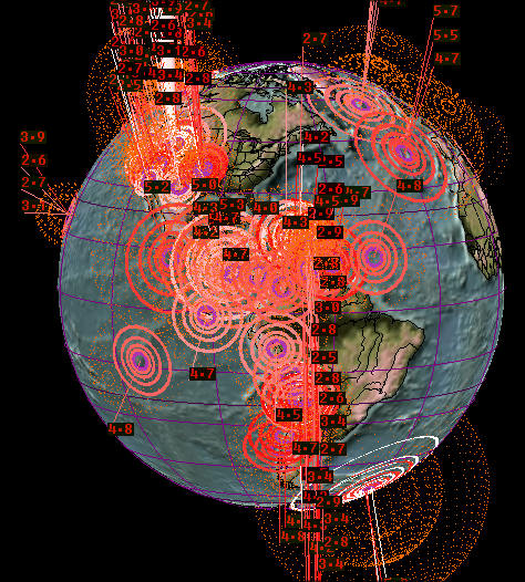
the Second Sun near the Earth will provoke the
GLOBAL EARTHQUAKE predicted as the 7th Apocalipse plague
|
|
|
|


|
|
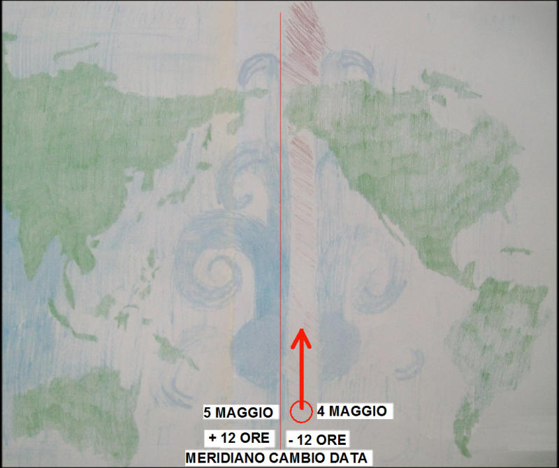
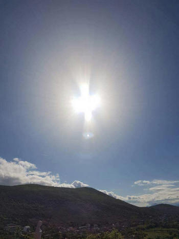
DOVE appeared on 2nd MAY, and decoded on the 8th of
MAY
 |
let's shift the references from 13-5 (FATIMAs
starting) to 13-10 (the CENTURY end):
 |
the DOVE is set NOW at 8-5-19: a GREAT SIGN
 |
|
|
|
|
|
since
11-11-2013
There will come
a day when
there will be two thrones,
but only one will sit the true successor of
Peter.
Anguera
3098 - 23/12/2008
two men would lead Peter's crown in recent times,
one
does not come from God
(and it shows ... the gesture: i love
satan ... and
the
looking)


Here cOme
the times I foretold 3.843
- July 8, 2013 Do you
live in the worst time
since
the GREAT
flood
|
the Orthodox
Patriarch Elijah Byzantine Catholic Orthodox
Patriarchate, in the name of God, One and
TRINO, declares the excommunication and the
curse of God in Galatians 1: 8-9 on
Francesco - Bergoglio, for his heresies,
and to all those who follow him, for betraying
Christ, God and the Holy Spirit, declaring servant
Antichrist leading to eternal damnation
those who follow him. Here
the statement
|
Gloria
Polo Ortiz says hell. After being struck
by lightning in the street, charred and
dead on the couch and
resuscitates all its organs are redone
before the doctors. It is sent back here to tell
her experience of hell. He
tells what 'we will see and we will live
during the Great Warning. Hell exists.
If you think you are right, pray and
be converted, that tells what is not
even imaginable. She thought she was
Catholic and just. click
for
video |
|
 |
 |
|
|
|
|
|
|
|

|
|
Schism
in the Catholic Church
VATICAN DESTRUCTION AND THE ANTICHRIST
COMING
MIDDLE EAST
WAR
USA INTERNAL ATTACKS
OTHER TERRORIST ATTACKS
ROME ATTACK
3RD WORLD WARi
THE ALLIANCES
NEW HEAVEN AND NEW SKY
-
The 1st RESURRECTION and JESUS CHRIST SECOND
COMING
|
le seguenti
dizioni sono state utilizzate in vari
messaggi iniziali (es. 2005), ma poi,
pian piano,
utilizzati anche i nomi veri
|
LEON = Iran |
the king nation = Italy/vatican |
|
Orso feroce = Russia |
seven hill town-city = Rome |
|
Nido dell'Orso = Mosca |
king = Pope |
|
Dragon = Cina |
great bird men = terrorists |
|
Eagle = USA |
palace = Saint Peter |
|
Earth of the Queen = England |
|
|
[L'OPPOSITORE]
COME
RICONOSCERE l'ANTICRISTO
|
|
Fire = bombs |
Saviour nation = Israel |
|
oriental snake= China/comunism |
Giant =
second sun |
|
bird = aircraft |
blac bird = vaiolo, pest,
radioactivity |
|
|
|
|
We see the issues
one by one. Keep in mind that
the issues are separate, so
the schism of the
Catholic Church,
has
to be
considered, in terms of time,
as in the other
events are held, as
explained by the messages.
NOTE: SINGLE messages
from point to point.
They are listed in order of
time. They were extracted
individual phrases from
the messages trying to place
them in a consistent pattern
divided by topics.
You
can
access the FULL text of
each message, where
indicated with (complete
message tracking or by clicking
on the year) |
|
complete messages:
Messages
2005
Messages
2006
Messages
2007
Messages
2008
Messages
2009
Messages
2010
Messages
2011
Messages
2012
-
Messages
2013
-
Messages 2014
-
Messages 2015 -
Messages
2016
- Prophetic
Messages 2005-2016
MIDDLE
EAST WAR
The Savior [ISRAEL] country
will suffer a lot, but when
he hears the defeat will
defend itself with weapons
that spread the fire in the
sky.
2501 - 26.03.2005
The city of Jerusalem will
be destroyed and when will
the great tribulation will
not be recognized;
will remain just a big desert 2,514 - 26.04.20055 (Luke 19,43)
A proud man will do deals
with Iran.
He seems to be a peacemaker,
but in truth it will be a
thorn for many nations.
The men of terror, led by
the one who has the
appearance of a prophet,
will bring suffering and
pain to the Eagle's Nest
[USA] and the country of the
Savior.
Here came the times I
foretold.
2516 - 30.04.2005 [Note: FIRST EVENT SAID that marks the beginning of the END
TIMES agreement in Geneva
USA - IRAN del 11/24/2013]
Israel will live the anguish
of a condemned, because they
will be surprised by the men
of terror.
2544 - 03/07/2005
Syria betray, but then will
drink his own poison.
2552 - 23.07.2005
Iran will be devastated by
Israel.
The earth will shake and
tremble for the great atomic
holocaust.
2557 - 04.08.2005
In Jerusalem, a temple will
be achieved.
The violence will grow 2,563 - 16.08.2005
The Savior's
city
will disappear [Bethlehem or Nazareth?], but men of faith will
be
saved
2,636 - 02/02/2006
It will
come
from Iran and men will be afraid
2,649- 04/03/2006
the kings of the East will join the great battle and humanity will lead a
heavy cross 2,694 - 16/06/2006
[Revelation - 9,
13 - the sixth trumpet]
On a mountain near Jerusalem
a frightening event will
happen 2695 - 17/06/2006
[3rd secret of Fatima?
see note]
the black bird will go to
Europe and where shall rest
will leave its mark of
destruction and death.
The violence will grow and
the men will bring a heavy
cross.
2718 - 10/08/2006
It is a disease and will be
worse than all those that
have ever existed.
Men will be contaminated and millions of dead bodies will be scattered
everywhere 2,719 - 12/08/2006
a large army will depart
from Mecca and where will
leave a trail of destruction
and death.
The wickedness of man will
be so great in the earth
that the Lord will bring
forward the day of the Final
Judgement.
2722 - 19/08/2006
The black bird will rest in
God's house. His strength
will cause destruction and
death.
2735 - 18/09/2006
Death will pass through the
holy city.
The terror will be immense.
There was throughout its
history a similar incident.
Pray.
I suffer because of what
awaits you.
2806 - 03.03.2007
The black bird will act and
will cause terror in all the
East.
Will go to the Eagle's Nest [USA]
and her children will suffer
2,846 - 03/06/2007
Israel will cry.
Death will pass and it will
be great destruction.
The great city will be
surrounded and its
inhabitants know a heavy
cross.
2899 - 06/10/2007
the ferocious bear
[Russia]
will feed the lion
[Iran]
and this will gain great strength to the attack
2902- 13/10/2007
The lion sons [Iran] will act with great fury against the house of God 3,006 -
05/06/2008
Jerusalem will be a story
that will attract the
world's attention.
For the Church will be a great suffering 3,027 - 17/07/2008
the furious lion [Iran] will attack the Church and cause great suffering to My
poor children 3.030 -
22/07/2008 The minds will
unite and will plan a major
attack
Israel, almost your entire
population will be
exterminated.
In the center of this
country will experience
great catastrophes.
In Jerusalem will happen
barbarians facts related to
religion and government.
Even in this nation the
earth-shaking many times.
October 21,
2007 [prophecies in Ferreira]
Jerusalem and many
neighboring cities will
experience a heavy cross.
Great shall be
the
devastation 3,145 - 10/04/2009
(Good Friday)
The Middle East will tremble
with the great atomic
holocaust.
3272-28-1-2010
There will come a day when the furious lion will lay at the foot of the dragon
[China] 3281
-17 February
2010. The union of the fairs
will bring great suffering
for my poor children
Bethlehem will live the
anguish of a condemned man.
The destruction will be
great and my poor children
will experience a heavy
cross.
3.311 - April 27,
2010
 |
|
USA Attacks and other
world wide places
The most frightening of the 15th century is
any reoccurrence.
2483 - 15.02.2005
The wise men came together and have prepared
in the laboratory destruction.
Men will see the death that exists to give 2,487 lives - 24.02.2005
The dragon [China] will face the eagle [USA] will launch and focus on her
children, causing the destruction of much of
its nest [country] 2,492 - 08.03.2005
nuclear and biological weapons will be used
by men with big beards and terror will
spread to various nations.
Know that there will be a big chaos in the world economy and only the meek and
humble of heart can survive 2,518 - 03.05.2005
Russia will make an agreement and this
agreement will be built something painful
for men.
The plague will not allow those who have
been contaminated to recognize.
Those who have been infected will be unable
to think.
2520 - 10.05.2005
// Russia will make an
agreement that will bring suffering and
death to many of my poor children.
3.810 - April 23, 2013
Smallpox will be used as a weapon against a
nation by men from the big beard.
2531 - 04.06.2005
Terror will come to a big city by water.
2547 - 12.07.2005
The men from the big beard are preparing a
great evil action.
In different areas and at the same time we
will be suffering and pain.
An army will explode 2,548 - 14.07.2005
Know that a famous city remain deserted.
Epidemic will take away from it many of its inhabitants and the other will die
2,559 - 09.08.2005
The men from the big beard will act in a big
city.
In the laboratory is of great destruction
weapon was prepared.
2575 - 13.09.2005
Men have prepared the virus of death and My
poor children will know great suffering.
There will be no barriers to hold its
advance.
Humanity is spiritually blind and came hard
times for you.
Kenya will need help.
2594 - 25.10.2005
The disease that resembles an immense field
with green herbs torment men.
The men of terror will be the offenders 2,607- 26.11.2005
An epidemic will spread to many nations and
My poor children will know a heavy cross.
2626 - 10/01/2006
Iberia will be the nest of the fairs, which
will bring great suffering for mankind.
2693 - 13/06/2006
The pain will be great for my poor children.
Chiloé: terror will pass.
2.697- 22/06/2006 The island of Chiloé is located in southern Chile.
It is a disease and will be worse than all
those that have ever existed.
Men will be contaminated and millions of dead bodies will be scattered
everywhere 2,719 - 12/08/2006
* The bird will be injured in the coast and
many nests are destroyed.
A mountain will fall and there will be great
destruction in many regions.
Russia will stumble and proud man will act with the strength given to him by
demonio.2.780 - 01.01.2007 [* eagle =USA]
The inhabitants of Philadelphia will live
moments of great difficulty.
Terror
will come.
The poison will spread and contaminate many
of my poor children.
2821 - 07.04.2007
The black bird will act and will cause
terror in all the East.
Will go to the Eagle's Nest [USA] and her children will suffer 2,846 - 03/06/2007
The men of terror will spread the poison and death will pass 2,847 - 05/06/2007
Men act of terror in the land of the Holy
Cross (Brazil).
The action will occur in the land of the
Divine.
2851 - 16/06/2007
The enemies will come in Manhattan and my
poor children will carry a heavy cross.
2924 - 01/12/2007
The great brain of humanity [USA] will fall
and people will feel the force of the great
commander of the East sword ... The rat
walking underground in the direction of the
white palace after passing through the two
rivers with wild animals names * 16
April
2008 [prophecies in Ferreira] * [River POTOMAC -> Army of POTOMAC - and
Anacostia River in Washington DC]
Men of great destruction will cause terror in the Holy Land Cross (Brazil)
3169 - 05/06/2009
the eagle will not fly quiet.
Its nest will tremble and there will be dismay 3.280 - 16 February 2010
The eagle's nest will be flooded and there
will be great destruction.
Terror will spread and My poor children will
weep and lament.
3.347 -
July 18,
2010
|
|
other WORLDWIDE
ATTACKS 2010 messages
for l'EUROPA
The wise men came together and have prepared
in the laboratory destruction.
Men will see the death that exists in order
to give life.
2487 - 24.02.2005
The richest men in the world will be in
trouble;
spread your hand to the poor and ask pardon.
Europe will touch
the lowest misery
2,517 - 01.05.2005
nuclear and biological weapons will be used
by men with big beards and terror will
spread to various nations.
2518 - 03.05.2005
One who spreads terror will be taken and the
mother of the terrible nations will be hit.
2536 - 14.06.2005
Smallpox will be used as a weapon against a
nation by men from the big beard.
The suffering will be great for many.
2531 - 04.06.2005
Terror will spread to various nations.
Taiwan will experience great pain 2519 - 07.05.2005
The men from the big beard will act in a big
city.
In the laboratory is of great destruction
weapon was prepared.
2575 - 13.09.2005
An army will march to Europe leaving a trail
of destruction and death.
2708 - 18/07/2006
It is a disease and will be worse than all
those that have ever existed.
Men will be contaminated and millions of
dead bodies will be scattered everywhere.
2719 - 12/08/2006
the black bird will go to Europe and where
shall rest will leave its mark of
destruction and death.
The violence will grow and the men will
bring a heavy cross.
2718 - 10/08/2006
The men from the big beard will act with
great fury.
Germany will suffer 2,743 - 07/10/2006
Approaching the time of the great battle.
A fast focus will fall upon men.
The
valve will open.
2820 - 05.04.2007
There will come a day when a famous
Brazilian city will be invaded.
The men will march furious and spread terror and death 2838 - 17/05/2007
Men act of terror in the land of the Holy
Cross (Brazil).
The action will occur in the land of the
Divine.
2851 - 16/06/2007
The men of terror will act with great fury.
A temple will be destroyed 2,878 - 18/08/2007
The West will tremble for the disastrous
event caused by the invisible enemy.
2923 - 27/11/2007
[Smallpox?
referred to in the message 2531 -
04.06.2005?
or an embedded virus in the Arctic ice?
see following message - God permits and wise
men will give the news.
It existed, does not exist and will exist.
The
answer will come.
Know that great are the mysteries of the
Lord.
Kneel in prayer.
2809 - 10.03.2007]
A revolt will cause destruction and death in
various countries of Europe.
3.265 - January 12,
2010
Europe will be poor, and everywhere there
will be great despair.
3.271 - January 26,
2010
A frightening will happen in Spain and
spread in various European countries.
France will drink the bitter cup of pain.
3.282 - 20 February
2010
A force devastating cross Europe causing
destruction and death.
3.303 - April 7,
2010
Death will pass through Europe and will
leave a big trail of destruction.
Similar suffering will be experienced by the
inhabitants of the Earth Holy Cross
(Brazil).
3.339 - July 2,
2010
Europe will bring a heavy cross.
Death and destruction will afflict My poor
children.
Geneva
will ask for help.
3.405 - 27 November
2010
Messages
2011
Messages
2012
-
Messages
2013
The death will cross several European
countries and the destruction will be great.
.
China will drink the bitter cup of pain.
You will see a great devastation.
Napoli
will ask for help.
3450 - March 12,
2011
Europe tremble.
Three countries ask for help 3.513 - July 19,
2011
A sorrowful event will happen in Europe.
Death will pass through several countries
and My poor children will weep and lament.
3.644 - April 24,
2012
A great revolt will rise in Europe and in
many countries there will be bloodshed.
3.663 - June 5,
2012
Death will pass through Europe, will pass
through several countries and the pain will
be great for my poor children.
3.741 - 24 November
2012
Europe's population will decline alarmingly.
Multitudes will seek relief in many regions
of the earth.
Rich and poor will go in the same direction
and eat the same bread.
Faith will be present in a few hearts 3.804 - April 13,
2013
Serious conflicts will spread to Brazil and
a serious and painful attack will draw the
world's attention.
3.886
- October 12,
2013
|
|
ROME ATTACK
The palace will be surprised by the invasion
and bloody furious men from the big beard.
2529 - 31.05.2005
The terror of the men reach the Vatican.
The square will be full of dead bodies.
Humanity will see the evil action of men
from the big beard.
The
Colosseum will collapse.
2553 - 24.07.2005
In a temple there will be a big explosion.
The men of terror will act with great fury 2597 - 01.11.2005
The city of seven hills will be destroyed 2,592 - 22.10.2005
[Revelation 17
Revelation 19]
St. Peter's land will be rubble -2,574 12.09.2005
The city of the seven hills will drink the
bitter cup of pain.
Will be bathed in the blood and terror will spread throughout 2775 - 21/12/2006
A great multitude will march in the
direction of the palace.
In their hearts, hatred and desire for
violence.
The king will be abandoned by many of his subjects 2862 - 12/07/2007
An attack against the house of the Lord will
draw the world's attention.
One who opposes Christ will act with great
fury.
2889 - 14/09/2007
One who opposes Christ will march with his
army, and come to the big city.
The throne of Peter will tremble 2,937 - 01/01/2008
Because of the black relic of men from the
big beard, there will be great pain for my
poor children.
The humanity will tremble before the painful
events that are to come.
2945 - 19/01/2008
VATICAN The stones will fall and the seat
will be forced to change seats.
The temple will be torn into two parts.
One in favor of the East and one in favor of
the West.
Even Rome will be rewarded for the
desecration of the house of the Lord.
23/01/2008 [prophecies Ferreira]
The men from the big beard will act against
the Christians.
The walls of the building will be stained with blood 2968 - 11/03/2008
the men followers of the false prophet will
march with great fury in the direction of
the holy temple.
There will be great destruction.
The Church will weep and complain.
On this day a lunar eclipse will be visible
2,975 - 23/03/2008
a great multitude, and we will march in
their hearts there is great desire for
revenge.
Bring suffering and pain to faithful men.
Profane the sanctuary, and the pain will be great for the Church of My Jesus.
2979 - 01/04/2008
The enemies of the Church will act with
great fury.
Burn a Sanctuary 2,995- 10/05/2008
Will rise the great relic and there will be a war between religious 2,997 -
13/05/2008 There will be great invasion and
in the palace you will see great destruction
- Matthew 24.15
The enemies will act with great fury against
the Church of My Jesus. The temples will be
invaded and there will be great destruction.
3011 - 17/06/2008
a great multitude, and will march with great
fury will cause great destruction.
Destroy the city of seven hills and occupy the throne of Peter 3018 - 01/07/2008
Russia will be a stone for many nations and Rome will be destroyed by fire
3.207 - August 29,
2009
The enemies will open doors and men from big beard will act with great fury
3.273 - January 30,
2010
Men act of terror against the Church.
They will try to destroy a temple.
Italy will be shaken by this painful event
3.319 - May 15,
2010
|
|
ITALY & FRANCE REVOLUTIONS & internal
problems
The richest men in the world
will be in trouble;
spread your hand to the poor
and ask pardon.
Europe will touch
the lowest misery
-
2,517 01.05.2005
Know that there will be a big chaos in the world economy and only the meek and
humble of heart can survive
2,518 - 03.05.2005
A great revolt will happen in Italy 2868 - 27/07/2007 The men will march
towards the Vatican and
cause pain and destruction.
The fate of Paris will
remember Sodom and Rome has
the fate of Gomorrah.
May 16, 2008 [prophecies in Ferreira]
Europe will rise up against the Church 3051 - 08/09/2008
Europe will become poor
spiritually and materially.
nations will disappear and
my poor children will carry
a heavy cross.
The worst is yet to come.
3144 - 07/04/2009
A sorrowful event will
happen in France and will
bring great suffering for
the Church.
The revolt is the result of disobedience 3,036 - 05/08/2008
A great revolt will rise in Europe and in many countries there will be
bloodshed 3.663 - June 5,
2012
[FRANCE] The Great Bear will
rise up against you.
September 8, 2007
[prophecies in Ferreira]
|
|
3rd World War
the struggle between the two
giants will claim the lives
of many innocents.
The fury of the beast will
leave thousands of corpses
scattered on the earth and
mankind will go through the
pain.
2474 - 25.01.2005
a proud man ordered its
construction and its
location made it possible to
make visible the presence of
the enemy * ..... is born
from injustice, but his end
will come from Justice #.
God is always the same.
He is Mercy and Justice.
2484 - 17.02.2005
[* note:
artificial satellites.
#
Cf. mess.
n.
2954 - 09/02/2008 What men have placed at the top will be consumed by fire]
The dragon [CHINA] will face
the eagle [USA] and launch
fire on his children,
resulting in the destruction
of much of its nest.
2492 - 08.03.2005
Russia trample many nations
and humanity will live
moments of great pain.
A great tragedy happen in
Korea.
The men are destroyed by
their own hands.
2536 - 14.06.2005
The leader of a great nation
will suffer an attack.
The danger of a third war becomes real 2540 - 25.06.2005
There will be war.
The evil deed of man will
cause death and destruction
in various countries.
2592 - 22.10.2005
A perverse
man will command a great
invasion.
The city of seven hills will be destroyed.
2007
Messages
The ferocious bear [Russia]
will go in search of its
space.
What men have placed in the top, God will do it fall to the ground
[satellites?] 2,788 - 20.01.2007
Russia will stumble and proud man will act with the strength given to him by
the devil 2,780 - 01.01.2007
The land of the queen will
live moments of great
tribulation.
A destructive fire will come
upon her.
2795 - 06.02.2007
A fast will cause
destruction in the fire of
the Holy Cross Terra
(Brazil).
Terror will spread and My
poor children will carry a
heavy cross.
2859 - 03/07/2007
fast and the land of King
will be hit in a fire will
come Earth queen.
2890 - 15/09/2007
The lack of understanding
between the three kings will
bring great suffering to My
poor children.
Three tents crolleranno.2.891 - 18/09/2007
Three giants join together to make war, but it will be a man of peace that
will contribute to the
peaceful coexistence between
them 2,893 - 22/09/2007
The seed of evil still
exists and the ferocious
bear feeds on it.
3065 - 11/10/2008
A frightening will happen in
Europe and will reach 3,246
three countries
simultaneously - November
28,
2009
The alliances -
the war start
The dragon [China] will face the eagle [USA]
will launch and fire on her children, causing the
destruction of much of its nest 2492 -
08.03.2005
A quick fire will reach the palace, but the
stone will not be broken.
2537 - 18.06.2005
The man will see a great
mystery: the night will become day.
The line, from water to water hidden ground will be broken (?).
Russia will stumble and will face a heavy cross 2,717 - 08/08/2006
From St. Petersburg released a plug that
will hurt my poor children.
The Guardian was born there and its branches
spread throughout the world.
Its venom is deadly, but the Lord will be in defense of His 2,778 - 26/12/2006
The stones will fall on the bear fierce.
2753 - 31/10/2006
fast fire will fall on the largest
cities 2,785 - 13.01.2007 Humanity will live the
anguish of a condemned man.
A serious conflict will lead to a major catastrophe.
It happens a frightening fact.
The ferocious bear will come to fighters 2,881- 25/08/2007
The lack of understanding between the three
kings will bring great suffering to My poor
children.
Three tents collapse 2,891 - 18/09/2007 [RUSSIA - CHINA - IRAN?]
The union of men from the big beard with
those of red will cause great pain to
humanity.
2,908 - 27/10/2007 [terrorists iran and china?]
A scary fact will happen in Paris, and will be repeated in Cuba 2911 - 03/11/2007
A fast fire will fall on Derby 2913 - 06/11/2007
Russia will stumble and proud man will act
with the strength given to him by the devil
2,780 - 01.01.2007
The bird [USA] will hurt
the coast and many nests are destroyed.
A mountain will fall and there will be great destruction in many regions.
[USA] The great brain of humanity will fall
and people feel the power of the sword of
the great commander of the East ... The rat
walking underground in the direction of the
white palace after passing through the two
rivers with wild animals * 16 names
April 2008 [prophecies Ferreira]
* [River POTOMAC -> Army of POTOMAC - and Anacostia River in Washington D.C.]
The great city that is at the side of the
Potomac * will live moments of great
affliction 3,428 - 20/01/2011
Minds will unite and will plan the large attack 3,030 - 22/07/2008 furious
lion attack the Church and cause great
suffering to My poor children
three nations will join you and persecute
the Church.
In these nations, the consecrated it will be prevented from performing his
duties, but the mighty hand of God will act
in favor of his Church 3038 - 09/08/2008
A quick cross fire the skies from different
countries of Europe.
Fall of a famous temple 3.189 - July 18,
2009
There will come a day when the ferocious
bear will join the Lion devouring.
Animal fury will fall on the Church and my
poor children will carry a heavy cross
consecrated 3135 - 17/03/2009
Messages
2005
Messages
2006
Messages
2007
Messages
2008
Messages
2009
Messages
2010
Messages
2011
Messages
2012
-
Messages
2013
-
Messages
2014
-
Messages 2015 -
Messages
2016
RUSSIAN ATTACK
(TO EUROPE)
Messages
2005
Three large stones from the east will fall on different countries, causing
destruction and death 2498 - 20.03.2005
The ferocious bear will go to various
nations and will arrive in Rome.
There he will leave his mark, and blood will flow on earth 2498 - 20.03.2005
The city of the seven hills will fall 2,502 - 29.03.2005
The richest men in the world will be in
trouble;
spread your hand to the poor and ask pardon.
Europe will touch 2,517 fund - 01.05.2005
nuclear and biological weapons will be used
by men with big beards and terror will
spread to various nations.
Know that there will be a big chaos in the world economy and only the meek and
humble of heart can survive 2,518 - 03.05.2005
Berlin will be rubble - 2,521 -
12.05.2005
St. Peter's land will be rubble - 2,574
-
12.09.2005
Rome will lose its glory and fame and suffering will be great for my poor
children 2,622 - 31.12.2005
Messages
2006
An army will march to Europe leaving a trail of destruction and death 2708 -
18/07/2006
The destruction will arrive in North Italy
and Denia [Spain] will bring a heavy cross.
2710 - 22/07/2006
The Netherlands will drink the bitter cup of
pain.
Death will pass 2,720 - 15/08/2006
Marseille will be destroyed 2,732 - 12/09/2006
Those who are on the banks of the Rhine will
ask for help.
2737 - 23/09/2006
Hungary will live moments of difficulty.
Terror will come and My poor children will weep and lament 2740 - 30/09/2006
Terror will come to Tampa and Tumbes 2,749 - 21/10/2006
Two
cities: white and pink.
Terror will come 2755 - 04/11/2006
Cries and moans are heard in Surat (India).
2756 - 07/11/2006
Terror will come to Cham and to the city of the great tower 2757 - 09/11/2006
Cries and moans are heard in Perth
(Australia).
2761 - 18/11/2006
Delhi will weep bitterly and my poor
children will carry a heavy cross.
2769 - 08/12/2006
Pray for the people of Hannover 2771 - 10/12/2006
Messages
2007
FRANCE - The Great Bear will rise up against
you.
September 2, 2007 - São José dos Pinhais / PR Message of Jesus [prophecies in
Ferreira]
There will come a day when the furious dragon will launch fire on Bear's nest
2930 - 15/12/2007- china shoots on fly
The inhabitants of Germany and Switzerland will know great sufferings 2,931 -
18/12/2007
It will explode War of Rome and will be few
survivors.
One who opposes Christ will bring suffering
and pain to all of Europe.
Peter's Throne will be empty 2939 - 05/01/2008
|
May
16, 2008 - São José
dos Pinhais / PR
Message of the Virgin Mary
to
Ferreira
A great mystery unearthed
bring many questions to man.
The light will shine on
Mount Sinai and the angel
sounds his trumpet toward the east,
bringing tremor primarily
to Israel. The city known
as "the sun entrance"
will lose its leader. The fate
of Paris will remember
Sodom and Rome
has the fate
of Gomorrah. |
Death will pass through several countries of Europe 3115 - 27/01/2009
Russia will be a stone for many nations and Rome will be destroyed by fire
3.207 - August 29,
2009
The day will come when Europe will stretch out his hand to the world as a
beggar who needs help 3.207 - August 29,
2009
Europe will be poor, and everywhere there will be great despair 3,271 -
January 26, 2010
a frightening event will happen in Geneva
and will be repeated in Pernambuco.
Geneva will live moments of great
tribulation.
The fury of the invisible enemy reach my poor children 3.302 - April 6,
2010
Death will pass through Europe and will
leave a big trail of destruction.
Similar suffering will be experienced by the inhabitants of the Earth Holy
Cross (Brazil) 3.339 - July 2,
2010
Europe will bring a heavy cross.
Death and destruction will afflict My poor
children.
Geneva
will ask for help.
3.405 - 27 November
2010
Amman (Jordan) will tremble.
The East will drink the bitter cup of pain 3432 - 29/01/2011
Europe tremble.
Three countries ask for help 3.513 - July 19,
2011
Europe's population will decline alarmingly.
Multitudes will seek relief in many regions
of the earth.
Rich and poor will go in the same direction
and eat the same bread.
Faith will be present in a few hearts 3.804 - April 13,
2013
The day will come when there will be a great
war.
4.047
- October 14,
2014
|
|
ANGUERA MESSAGES from Pedro Regis
the prophetic messages are mostly foretold
starting from year 2005 |
|
complete messages ANGUERA 1987 - 2004
-
word
-
pdf |
complete messages ANGUERA 2013
-
word -
pdf |
|
complete messages ANGUERA 2005
- 2012 -
word
-
pdf |
complete messages ANGUERA
2005-2015 -
WORD
-
PDF |
|
|
|
|
Messages 1987-88-89 |
Messages 2005 |
|
Messages 1990-91
|
Messages 2006 |
|
Messages 1992-93 |
Messages 2007 |
|
Messages 1994-95 |
Messages 2008 |
|
Messages 1996-97 |
Messages 2009 |
|
Messages 1998-99 |
Messages 2010 |
|
Messages 2000-2001 |
Messages 2011 |
|
Messages 2002-03-04 |
Messages 2012 |
|
|
Messages 2013 |
|
the more important
prophetic messages before
2005 |
Messages 2014 |
|
messages 458 per provare la
veridicità delle apparizioni -
pdf |
Messages 2015 -
Messages 2016 |
|
original website
www.apelosurgentes.com.br
|
|
Dear children,
the task
that I have entrusted
to you is great.
Bring the world all my
messages! I
need each one of you.
(N.
1000 -
08.29.1995) |
|
The
Holy Virgin MAry
releases
the messages contained in
this text appears in Brazil,
Bahia State in Fazenda
Malhada Nova,
Anguera Hall of Pedro
Regis. The apparitions
began September 29, 1987
and still exist today.
In the beginning the apparitions
took place only on
Saturdays, later also
added on Tuesday after
a third appearance on any
day of the week, only
for the seer. I am
23 years, so far with
an impressive number of messages
(more than 3900)
carefully numbered.
Since 2005 the amount of
those with prophetic
content has grown.
Since 2010 there has
been a change in the
structure of language, which went
from an indeterminate
future to "now."
What caught the attention of many
readers were the prophetic
messages relating to
disasters of Madeira and
the earthquake been caused
after a few weeks.
|
|
www.apelosurgentes.com.br
Pedro Régis it has
grown humble farmer
in a small ranch of the
interior of Bahia, in
a place that surely were it
not for the manifestation
of Mary would be nothing
but a sleepy town and
forgot the Bahian
wilderness. He attended the
Magisterium in Anguera.
Son of Jonas Sr.
and gives Amalia,
people who enjoy extreme
credibility in the community,
has 14 brothers.
They are simple people,
friendly, welcoming
and good will, converse
with all those who go
there, exercising a true
apostolate and his son
Pedro to Our Lady
love. They live cultivating
beans, millet and cassava.
Their life has changed
enough since the beginning
of the apparitions. Recite
the Rosary every day,
fast in Friday on
bread and water, and try to
follow faithfully
the path of
Christ

 |
|
the reason why the Holy Virgin Mary
appears
Message n.2.578 -
22.09.2005
Dear children, these are
the times of great
tribulations. Trust in the
Lord. Your strength is
in Him who sees in secret
and knows each of you by
name. Be careful. Do
not turn away from the truth.
God has sent me to you
to warn you of
everything that has to happen.
What I say is not to make
you afraid. I want to
prepare you so that you can
withstand the weight of the cross.
If you pray you will
understand that my appeals
are not of fear, but
warning that leads you to
hope. Keep balances.
Those who plan against
my plans will not get
anything. Those who belong
I know understand my
call. Kneel in prayer.
Next. This is the message I
give you today in the name
of the Holy Trinity.
Thanks for allowing me to
reunite you here once
again. I bless you in
the name of the Father,
the Son and the Holy
Spirit.
Amen. Be at peace. |
|
|
3.858 - August 10, 2013 -
Enhance your life and not remain silent in front
of deceitful campaigns against life and against
the sanctity of marriage. Be an example of faith and
courage to others. God needs your yes. The
powerful of this world create laws to offend the
Creator. The laws against life aim to remove
the Lord from the society and make men slaves of
the devil. You are of God. Defend what is
the Lord's. Your silence strengthens the enemies
of God. Say yes to life. Say no to the
killing of the innocent. All the evil that you do
against the small of God will lead to eternal
perdition.

http://www.messaggidianguera.net
altri link da visitare:
http://www.bookofthetruth.com


|
|
|
no copyright on these pages -
copy and reforward
 |
|
|

|
 |
|